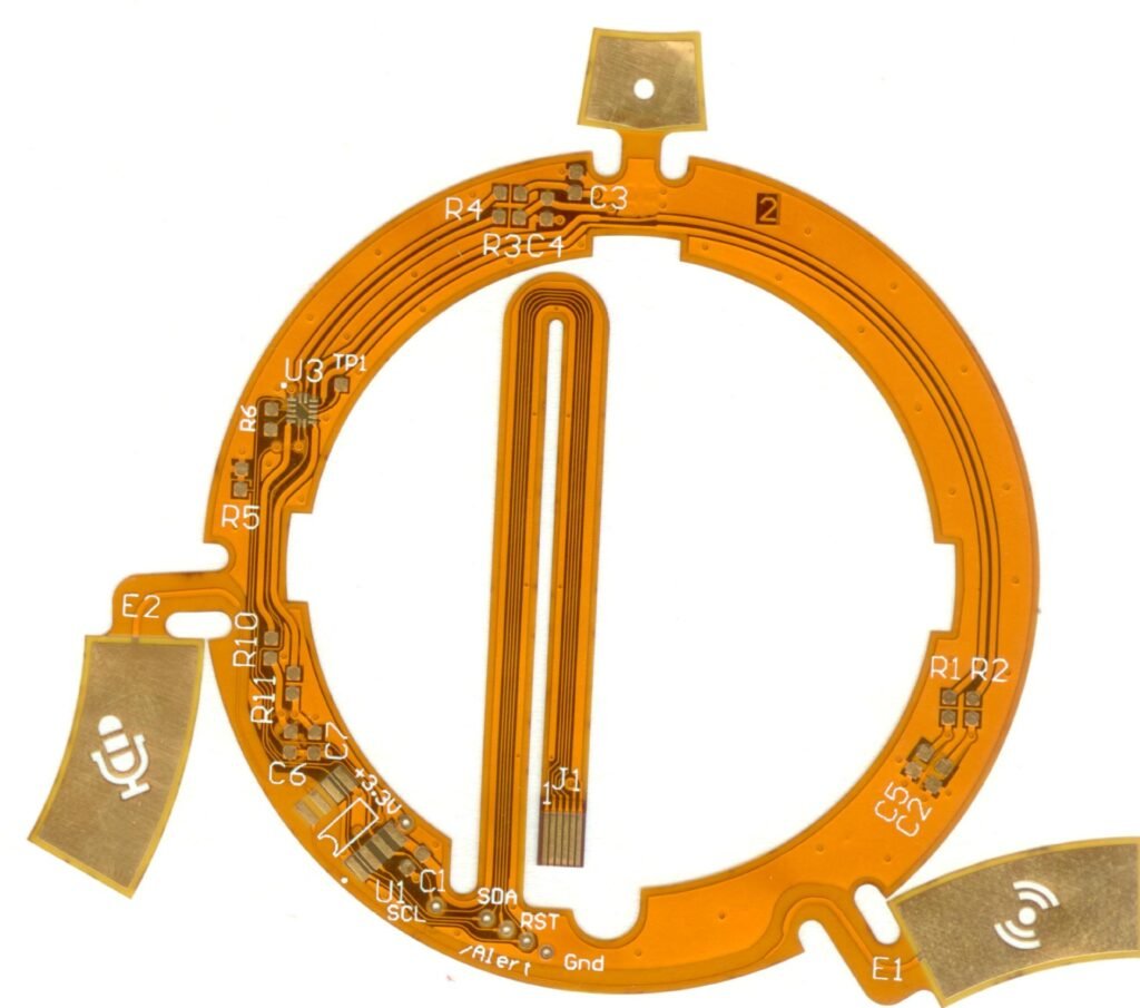
The main material used for Flex PCBs (Flexible Printed Circuit Boards) is:
🟧 1. Polyimide (PI) – The Industry Standard
Polyimide is the most commonly used base material for high-quality flex PCBs due to its excellent flexibility, thermal stability, and chemical resistance.
| Feature | Details |
|---|---|
| Base Film | Polyimide (e.g., DuPont™ Kapton®, Shengyi, etc.) |
| Typical Thickness | 0.0125 mm – 0.100 mm (most common: 0.025–0.05 mm) |
| Max Operating Temp | 250–300°C |
| Key Strengths | High flexibility, solder-resistance, durability |
| Use Cases | Aerospace, medical, automotive, wearables, etc. |
🟦 2. Copper Foil
- Used for circuit traces.
- Types: Rolled Annealed (RA) or Electro-Deposited (ED)
- Typical thickness: 0.5 oz, 1 oz, or 2 oz (17.5 µm – 70 µm)
RA Copper is preferred for flex circuits because of its ability to withstand repeated bending.
🟨 3. Adhesives (optional)
- Used to bond copper to the polyimide layer or attach coverlays.
- Types: Acrylic, Epoxy, or Adhesiveless (laminated directly)
- Some advanced flex PCBs are adhesiveless, improving flexibility and heat resistance.
🟩 4. Coverlay (Cover Film)
- Typically also made of polyimide film + adhesive.
- Protects circuits from moisture, dust, mechanical stress, and oxidation.
- Alternative in some designs: solder mask, though coverlay is more robust in flexing.
Want a Recommendation?
If you’re designing a high-flex, high-reliability circuit (e.g., for medical, automotive, or aerospace), use:
- PI base film (25–50 µm)
- RA copper (1 oz)
- Coverlay instead of solder mask
Let me know your project type, and I can help you pick the best material stack!


